
Page 486 - 2006 HARLEY FLSTCI SERVICE MANUAL
P. 486
B-23
4 Appendix B
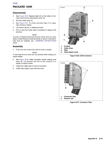
Figure B-36. ECM Connector Figure B-37. Connector Tabs
3 3 1
Conduit Cable strap Tabs Clear plastic cover 2 Connector tabs Retainer tab
s0542x8x 2 1 1. 2. 3. 4. s0543x8x 1. 2.
A series of Packard Electrical Terminal Crimp Tools are avail-
CRIMPING INSTRUCTIONS able to install Packard socket terminals on wires. If new termi- NOTE In next step be sure wires are not pinched while mating con- See Figure B-36. Mate connector halves making sure wires are not pinched and end of wire conduit (1) is
See Figure B-37. Pry three connector tabs (1) to sepa-
See Figure B-36. Depress tabs (3) on the sides of con-
Pull on wire from back side of connector to expose wire
NOTE
PACKARD 100W Disassembly nector and remove clear plastic cover (4). Remove cable strap (2). rate connector halves. Lift retainer tab (2). to release terminal. terminal. nals must be installed, see Push wire into correct hole until terminal is seated. inside connector halves. Install new cable strap on end of connector. Install clear plastic cover over terminals.
HOME 1. 2. 3. 4. 5. below. Assembly 1. nector halves. 2. 3. 4.