
Page 484 - 2006 HARLEY FLSTCI SERVICE MANUAL
P. 484
f2202x8x Secondary Lockpin B-21
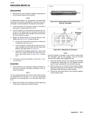
Figure B-29. Packard Micro 64 Terminal Remover
6 6 12 12 Appendix B
(Part No. HD-45928). Small Hole 5 4 3 11 10 9 Figure B-30. Mating End of Connector NOTE Once the terminal is removed it may not lock in place when first reinstalled. Until the lock engages, move the terminal Since the terminal remover tool releases two terminals simultaneously, repeat step 2 on the adjacent terminal even if it was not pulled from the connector housing. With the center ear on the head of the secondary lockpin facing the mating end of the connector, push lockpin in until head is flush with the connector housing. Push the pin and socket halves of the connector together
1 2 8 7 back and forth slightly while wiggling the lead. until the latches “click.”
1 7
HD45929
3. 4. 5.
Remove Figure B-31.
PACKARD MICRO 64 Bend back the external latches slightly and separate the pin and socket halves of the connector. NOTE differentiate between the speedometer and tachometer connectors, note that the speedometer connector has a sec- ond length of conduit leading to the odometer reset switch. Locate the head of the secondary lockpin on one side of the connector housing. See Figure B-30. Insert the blade of a small screwdriver between the cen- ter ear of the lockpin and the connector housing and gently pry out lockpin. When partially removed, pull lock- pin from connector housing. Obtain the Packard Micro 64 Terminal Remover (HD- 45928). See Figure B
HOME Disassembly 1. To 2. 3. 4. a. b. c. 5. Assembly 1. B-30. 2.