
Page 919 - 2006 HARLEY FLSTCI SERVICE MANUAL
P. 919
3.31 3.19 BOTTOM END OVER- TOP END OVERHAUL:
Figure 3-185. Connecting Rod Bearing Clearance
Figure 3-186. Connecting Rod Side Play INSTALLATION OVERVIEW 3.17
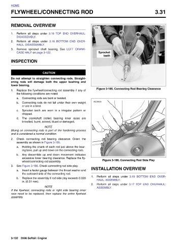
Sprocket teeth Perform all steps under HAUL: ASSEMBLY. Perform all steps under ASSEMBLY.
7466 d0238x3x
1. 2.
YWHEEL/CONNECTING ROD
TOP END OVERHAUL: 3.18 BOTTOM END OVER- LEFT CRANK- Connecting rods do not fall under their own weight Sprocket teeth are worn in a irregular pattern or The crankshaft (roller) bearing inner races are Holding the shank of each rod just above the bear- ing bore, pull up and down on the connecting rods. Any discernible up and down movement indicates excessive lower bearing clearance. Replace the fly- Insert a feeler gauge between the thrust washer and Replace the assembly if rod side play exceeds 0.020
REMOVAL OVERVIEW 3.16 Perform all steps under DISASSEMBLY. Perform all steps under HAUL: DISASSEMBLY. Remove sprocket shaft bearing. See CASE HALF on page 3-122. CAUTION Do not attempt to straighten connecting rods. Straight- ening rods will damage both the upper bushing and Replace the flywheel/connecting rod assembly if any of the following conditions are noted: Connecting rods are bent or twisted. or are in a bind. chipped. brinelled, burnt, scored, blued or damaged. NOTE Bluing on connecting rods is part of the hardening process and is considered a normal condition. Check connecting rod bearing clearance. Orient the assembly as
HOME FL 1. 2. 3. INSPECTION lower bearing. 1. a. b. c. d. 2. a. b. 3. a. b. assembly. 3-132