
Page 43 - GIGABYTE Service Manual-v3.0-110101
P. 43
2.7 VCORE,VDDQ,VCC3 and VCC
The repair step of voltage short is to remove the components which connected to the
voltage one by one until the short component is identified.
VCORE: PWM, Driver, MOSFET, NB, SB
VDDQ: MOSFET, NB, SB
VCC3: NB, SB, BIOS, CLK GEN, SOUND, PWM
VCC5: SB, BIOS, I/O, 1394, SATA, RAID, PWM, SOUND
The component removing rules:
01. From low pins components to high pins components.
02. from high damage rate to low damage rate.
03. From easy replacing to difficult replacing.
04. Remove PQFP packing chips before BGA packing chips.
Don’t solder new components before the short is identified.
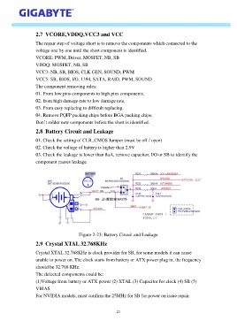
2.8 Battery Circuit and Leakage
01. Check the setting of CLR_CMOS Jumper (must be off / open)
02. Check the voltage of battery is higher than 2.9V
03. Check the leakage is lower than 8uA, remove capacitor, I/O or SB to identify the
component causes leakage.
Figure 2-23: Battery Circuit and Leakage
2.9 Crystal XTAL 32.768KHz
Crystal XTAL 32.768KHz is clock provider for SB, for some models it can cause
unable to power on. The clock starts from battery or ATX power plug in, the frequency
should be 32.768 KHz.
The defected components could be:
(1)Voltage from battery or ATX power (2) XTAL (3) Capacitor for clock (4) SB (5)
VBIAS
For NVIDIA models, must confirm the 25MHz for SB for power on issue repair.
21