
Page 48 - GIGABYTE Service Manual-v3.0-110101
P. 48
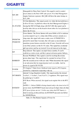
Manageability Sleep State Control: This signal is used to control

                                   power planes to the Intel AMT sub-system. If no Intel Management
                   SLP_M#
                                   Engine firmware is present, SLP_M# will have the same timings as
                                   SLP_S3#.
                                   S4 State Indication: This signal asserts low when the host platform is

                                   in S4 or S5 state. In platforms where the Intel Management Engine is
                   S4_STATE#    forcing the SLP_S4# high along with SLP_M#, this signal can be
                                   used by other devices on the board to know when the host platform is
                                   below the S3 state.

                                   Power Button: The Power Button will cause SMI# or SCI to indicate
                                   a system request to go to a sleep state. If the system is already in a
                                   sleep state, this signal will cause a wake event. If PWRBTN# is
                   PWRBTN#
                                   pressed for more than 4 seconds, this will cause an unconditional
                   PWRBTSW
                                   transition (power button override) to the S5 state. Override will occur
                                   even if the system is in the S1–S4 states. This signal has an internal
                                   pull-up resistor and has an internal 16 ms de-bounced on the input.

                                   Ring Indicate: This signal is an input from a modem. It can be
                   RI#
                                   enabled as a wake event, and this is preserved across power failures.
                                   Resume Well Reset: This signal is used for resetting the resume
                                   power plane logic. This signal must be asserted for at least 10 ms

                   RSMRST#         after the suspend power wells are valid. When deasserted, this signal
                                   is an indication that the suspend power wells are stable. And the
                                   power ok signal of IO VCCH.
                                   PCI Express* Wake Event: Sideband wake signal on PCI Express
                   WAKE#
                                   asserted by components requesting wake up.
                                   Internal Voltage Regulator Enable: This signal enables the internal
                   INTVRMEN    VccSus1_1, VccSus1_5 and VccCL1_5 regulators. This signal must
                                   be pulled-up to VccRTC.

                                   RTC Reset: When asserted, this signal resets register bits in the RTC
                                   well.
                                   NOTES: 1. Unless CMOS is being cleared (only to be done in the G3

                   RTCRST#         power state); the RTCRST# input must always be high when all other
                                   RTC power planes are on. 2. In the case where the RTC battery is
                                   dead or missing on the platform, the RTCRST# pin must rise before
                                   the RSMRST# pin.

                                       Table 2-8: The Related Signals of Power On


                                                            26