
Page 53 - GIGABYTE Service Manual-v3.0-110101
P. 53
DES Circuit Section: (example: PWM3_CR)
The Section includes Q50, Q51, Q55, Q75, Q9, DD3, DD4, DD7 and R, C. If
PWM3_CR is high, DD7 LED brightens, indicating PHASE 3 is working. Then PWM3
connects to PWM3_DRV which connects to DU2 PWM drive. PHASE4, PHASE5,
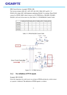
PHASE 6, all work at the same way (See Table 3-1: PWM PHASE Control Table)
Table 3-1: PWM PHASE Control Table
Figure 3-5: VCORE Section 4
3.1.2 The definition of PWM signals
Example: EP45-UD3R
Check the impedance by multi-meter on each pin of PWM and identify which resistor
or capacitor is defected. The definition of PWM signals is as below:
31