
Page 52 - GIGABYTE Service Manual-v3.0-110101
P. 52
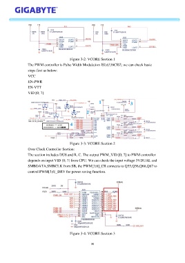
Figure 3-2: VCORE Section 1
                   The PWM controller is Pulse Width Modulation ISL6336CRZ; we can check basic
                   steps first as below:

                   VCC
                   EN-PWR
                   EN-VTT
                   VID [0; 7]


                                              Figure 3-3: VCORE Section 2
                   Over Clock Controller Section:
                   The section includes DU8 and R, C. The output PWM_VID [0; 7] to PWM controller
                   depends on input VID [0; 7] from CPU. We can check the input voltage 3VDUAL and

                   SMBDATA,SMBCLK from SB, the PWM[3;6]_CR connects to Q55,Q56,Q66,Q67 to
                   control PWM[3;6]_DRV for power saving function.


                                              Figure 3-4: VCORE Section 3


                                                            30