
Page 57 - GIGABYTE Service Manual-v3.0-110101
P. 57
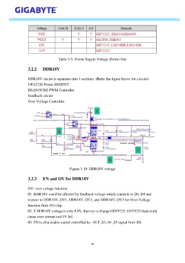
Table 3-5: Power Supply Voltage (Power On)


                   3.2.2     DDR18V


                   DDR18V circuit is separated into 4 sections: (Refer the figure below for circuits)
                   UPA2726 Power MOSFET
                   ISL6545CBZ PWM Controller

                   Feedback circuit
                   Over Voltage Controller


                                              Figure 3-10: DDR18V voltage

                   3.2.3     EN and OV for DDR18V


                   OV: over voltage function
                   01. DDR18V could be affected by feedback voltage which connects to D8, D9 and
                   resistor to DDR18V_OV1, DDR18V_OV2, and DDR18V_OV3 for Over Voltage
                   function from I/O chip.

                   02. If DDR18V voltage is only 0.8V, then try to change GD75232. GD75232 bad could
                   cause over current and 5V fail.
                   03. EN is chip enable signal controlled by –SLP_S3,-S4_S5 signal from SB.


                                                            35