
Page 291 - FUNDAMENTALS OF COMPUTER
P. 291
NPP Number System, Boolean Algebra and Logic Circuits 291
The truth table for 3-input AND Gate is : VrZ BZnwQ> dmbo AND JoQ> H$s gË` Vm{bH$m Bg
àH$ma ~ZoJr…
A B C Y=A.B.C
0 0 0 0
0 0 1 0
0 1 0 0
0 1 1 0
1 0 0 0
1 0 1 0
1 1 0 0
1 1 1 1
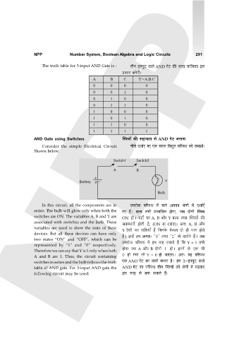
AND Gate using Switches pñdMm| H$s ghm`Vm go AND JoQ> ~ZmZm
Consider the simple Electrical Circuit ZrMo Xem©E JE EH$ gab {dÚwV n[anW H$mo g_Pmo…
Shown below: NPP
Switch1 Switch2
A B
Battery Y
Bulb
In this circuit, all the components are in Cnamoº$ n[anW _| gmao Ad`d loUr _| Xem©E±
series. The bulb will glow only when both the JE h¢Ÿ& ~ë~ V^r àÁd{bV hmoJm, O~ XmoZm| pñdM
switches are ON. The variables A, B and Y are ON hmoŸ& `hm± na A, B Am¡a Y ~ë~ VWm pñdMm| H$s
associated with switches and the bulb. These AdñWmE± hmoVr h¡, (ON `m OFF)& AV… A, B Am¡a
variables are used to show the state of these Y Eogr Ma am{e`m± h¢ {OZHo$ Ho$db Xmo hr _mZ hmoVo
devices. But all these devices can have only
two states “ON” and “OFF”, which can be h¢Ÿ& BÝh| h_ H«$_e… '0' VWm '1' go Xem©Vo h¢Ÿ& A~
represented by “1” and “0” respectively. Cnamoº$ n[anW _| h_ H$h gH$Vo h¢ {H$ Y = 1 V^r
Therefore we can say that Y is 1 only when both hmoJm O~ A Am¡a B XmoZm| 1 hmoŸ& BZ_| go EH$ ^r
A and B are 1. Thus, the circuit containing 0 hmo J`m Vmo Y = 0 hmo OmEJmŸ& AV… `h n[anW
switches in series and the bulb follows the truth EH$ AND JoQ> H$m H$m`© H$aVm h¡Ÿ& h_ 3-BZnwQ> dmbo
table of AND gate. For 3-input AND gate the AND JoQ> H$m n[anW VrZ pñdMm| H$mo loUr _| aIH$a
following circuit may be used: Bg Vah go ~Zm gH$Vo h¢…