Page 295 - FUNDAMENTALS OF COMPUTER
P. 295

NPP


                  NPP               Number System, Boolean Algebra and Logic Circuits              295
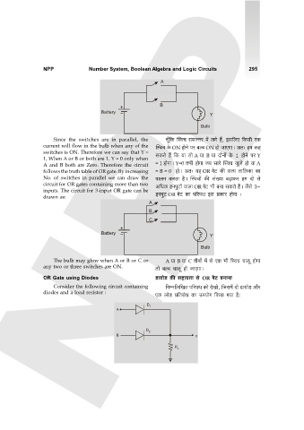
                                                                A


                                                                B
                                         Battery
                                                                                   Y
                                                                                Bulb

                      Since the switches  are  in parallel,  the  My±{H$ pñdM g_mÝVa _| bJo h¢, Bg{bE {H$gr EH$
                  current will flow in the bulb when any of the  pñdM Ho$ ON hmoZo na ~ë~ ON hmo OmEJmŸ& AV… h_ H$h
                  switches is ON. Therefore we can say that Y =
                  1, When A or B or both are 1. Y = 0 only when  gH$Vo h¢ {H$ `m Vmo A `m B `m XmoZm| Ho$ 1 hmoZo na Y
                  A and B  both are  Zero. Therefore  the circuit  = 1 hmoJmŸ& Y=0 V^r hmoJm O~ gmao pñdM Iwbo hmo `m A
                  follows the truth table of OR gate. By increasing  = B = 0  hmoŸ& AV… `h OR JoQ> H$s gË` Vm{bH$m H$m
                  No.  of  switches in parallel  we  can  draw the  nmbZ H$aVm h¡Ÿ& pñdMm| H$s g§»`m ~‹T>mH$a h_ Xmo go
                  circuit for OR gates containing more than two  A{YH$ BZnwQ>m| dmbm OR JoQ> ^r ~Zm gH$Vo h¢Ÿ& O¡go 3-
                  inputs. The circuit for 3-input OR gate can be
                  drawn as:                                   BZnwQ> OR JoQ> H$m n[anW Bg àH$ma hmoJm …
                                                           A
                                                           B
                                                           C

                                         Battery
                                                                                   Y

                                                                                Bulb

                      The bulb may glow when A or B or C or       A `m B `m C VrZm| _| go EH$ ^r {ñdM Mmcy hmoJm
                  any two or three switches are ON.           Vmo ~ë~ Mmcy hmo OmEJmŸ&

                  OR Gate using Diodes                        S>m`moS> H$s ghm`Vm go OR JoQ> ~ZmZm
                      Consider the following circuit containing   {ZåZ{b{IV n[anW H$mo XoImo, {Og_| Xmo S>m`moS> Am¡a
                  diodes and a load resistor :                EH$ bmoS> à{VamoY H$m Cn`moJ {H$`m J`m h¡…

                                                           D 1
                                               A


                                                          D
                                                           2
                                               B                             Y
                                                                     R
                                                                       L
   290   291   292   293   294   295   296   297   298   299   300