
Page 99 - eProceeding - IRSTC & RESPEX 2017
P. 99
Syamsul Anuar / JOJAPS – JOURNAL ONLINE JARINGAN COT POLIPD
He deduces that a big error on height value might be caused by the auto tie points that were not well established, which were
being effected due to the image resolution, color balancing and image quality itself such as blurring effects. Ahmad (2011), in
his research using low altitude UAV for digital mapping, the differences in height coordinates between ground height from GPS
and ground height from Erdas Imagine software product reached 1.595 meters. In his research, he used a small format digital
camera and high accuracy could be achieved by the large format metric camera.
2. Methodology
Generally, there are four (4) phases or stages involved in this study. Each phase of the study describes as the procedure to
achieve the objective of the study. Phase 1 is the preparation stage. This stage involved the preparation to the instruments or
equipment’s used, the software used, the study area, the camera used and the design of the flight planning. Phase 2 is data
acquisition. The main data need to be collected at the study area are UAV images and GCPs. In phase 3, there are several
software will be used to do the data processing. Agisoft PhotoScan version 0.9.0 and Global Mapper version 15.2.3 are used to
process UAV images. Topcon Tools version 8.2.3 is used to convert GPS ellipsoidal height to GPS orthometric height. The last
phase is data analysis. In this stage, qualitative and quantitative assessment will be evaluated.
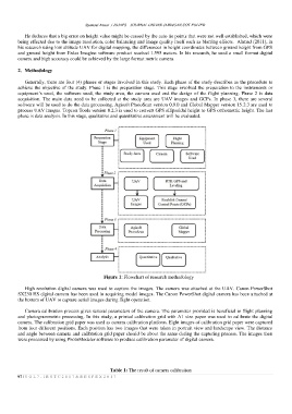
Figure 1: Flowchart of research methodology
High resolution digital camera was used to capture the images. The camera was attached at the UAV. Canon PowerShot
SX230 HS digital camera has been used in acquiring model images. The Canon PowerShot digital camera has been attached at
the bottom of UAV to capture aerial images during flight operation.
Camera calibration process gives several parameters of the camera. The parameter provided is beneficial in flight planning
and photogrammetric processing. In this study, a printed calibration grid with A1 size paper was used to calibrate the digital
camera. The calibration grid paper was used as camera calibration platform. Eight images of calibration grid paper were captured
from four different positions. Each position has two images that were taken in portrait view and landscape view. The distance
and angle between camera and calibration grid paper should be about the same during the capturing process. The images then
were processed by using PhotoModeler software to produce calibration parameter of digital camera.
Table 1: The result of camera calibration
97 | V O L 7 - I R S T C 2 0 1 7 & R E S P E X 2 0 1 7