
Page 191 - Handout of Computer Architecture (1)..
P. 191
■ ALU: The control unit controls the operation of the ALU by a set of control signals. These signals activate
various logic circuits and gates within the ALU.
■ System bus: The control unit sends control signals out onto the control lines of the system bus (e.g.,
memory READ). The control unit must maintain knowledge of where it is in the instruction cycle. Using
this knowledge, and by reading all of its inputs, the control unit emits a sequence of control signals that
causes micro- operations to occur. It uses the clock pulses to time the sequence of events, allowing time
between events for signal levels to stabilize.
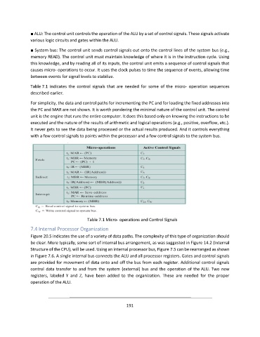
Table 7.1 indicates the control signals that are needed for some of the micro- operation sequences
described earlier.
For simplicity, the data and control paths for incrementing the PC and for loading the fixed addresses into
the PC and MAR are not shown. It is worth pondering the minimal nature of the control unit. The control
unit is the engine that runs the entire computer. It does this based only on knowing the instructions to be
executed and the nature of the results of arithmetic and logical operations (e.g., positive, overflow, etc.).
It never gets to see the data being processed or the actual results produced. And it controls everything
with a few control signals to points within the processor and a few control signals to the system bus.
Table 7.1 Micro- operations and Control Signals
7.4 Internal Processor Organization
Figure 20.5 indicates the use of a variety of data paths. The complexity of this type of organization should
be clear. More typically, some sort of internal bus arrangement, as was suggested in Figure 14.2 (Internal
Structure of the CPU), will be used. Using an internal processor bus, Figure 7.5 can be rearranged as shown
in Figure 7.6. A single internal bus connects the ALU and all processor registers. Gates and control signals
are provided for movement of data onto and off the bus from each register. Additional control signals
control data transfer to and from the system (external) bus and the operation of the ALU. Two new
registers, labeled Y and Z, have been added to the organization. These are needed for the proper
operation of the ALU.
191