
Page 193 - Handout of Computer Architecture (1)..
P. 193
■ Interrupt control: This module handles multiple levels of interrupt signals.
■ Serial I/O control: This module interfaces to devices that communicate 1 bit at a time. Table 20.2
describes the external signals into and out of the 8085. These are linked to the external system bus. These
signals are the interface between the 8085 processor and the rest of the system (Figure 7.8).
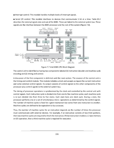
Figure 7.7 Intel 8085 CPU Block Diagram
The control unit is identified as having two components labeled (1) instruction decoder and machine cycle
encoding and (2) timing and control.
A discussion of the first component is deferred until the next section. The essence of the control unit is
the timing and control module. This module includes a clock and accepts as inputs the current instruction
and some external control signals. Its output consists of control signals to the other components of the
processor plus control signals to the external system bus.
The timing of processor operations is synchronized by the clock and controlled by the control unit with
control signals. Each instruction cycle is divided into from one to five machine cycles; each machine cycle
is in turn divided into from three to five states. Each state lasts one clock cycle. During a state, the
processor performs one or a set of simultaneous micro- operations as determined by the control signals.
The number of machine cycles is fixed for a given instruction but varies from one instruction to another.
Machine cycles are defined to be equivalent to bus accesses.
Thus, the number of machine cycles for an instruction depends on the number of times the processor
must communicate with external devices. For example, if an instruction consists of two 8-bit portions,
then two machine cycles are required to fetch the instruction. If that instruction involves a 1-byte memory
or I/O operation, then a third machine cycle is required for execution.
193