
Page 190 - Handout of Computer Architecture (1)..
P. 190
into the MBR and increment the PC. The control unit does this by sending the following control signals
simultaneously:
■ A control signal that opens gates, allowing the contents of the MAR onto the address bus;
■ A memory read control signal on the control bus;
■ A control signal that opens the gates, allowing the contents of the data bus to be stored in the MBR;
■ Control signals to logic that add 1 to the contents of the PC and store the result back to the PC. Following
this, the control unit sends a control signal that opens gates between the MBR and the IR. This completes
the fetch cycle except for one thing:
The control unit must decide whether to perform an indirect cycle or an execute cycle next. To decide
this, it examines the IR to see if an indirect memory reference is made. The indirect and interrupt cycles
work similarly. For the execute cycle, the control unit begins by examining the opcode and, on the basis
of that, decides which sequence of micro- operations to perform for the execute cycle.
A Control Signals Example To illustrate the functioning of the control unit, let us examine a simple
example.
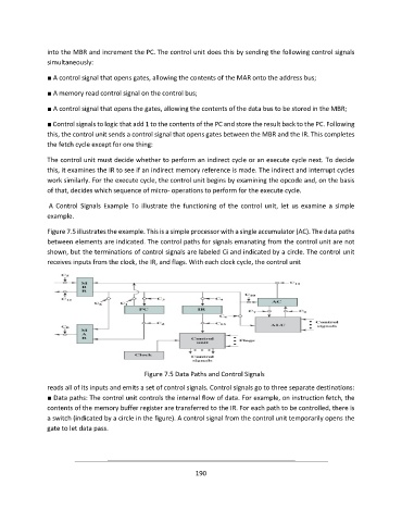
Figure 7.5 illustrates the example. This is a simple processor with a single accumulator (AC). The data paths
between elements are indicated. The control paths for signals emanating from the control unit are not
shown, but the terminations of control signals are labeled Ci and indicated by a circle. The control unit
receives inputs from the clock, the IR, and flags. With each clock cycle, the control unit
Figure 7.5 Data Paths and Control Signals
reads all of its inputs and emits a set of control signals. Control signals go to three separate destinations:
■ Data paths: The control unit controls the internal flow of data. For example, on instruction fetch, the
contents of the memory buffer register are transferred to the IR. For each path to be controlled, there is
a switch (indicated by a circle in the figure). A control signal from the control unit temporarily opens the
gate to let data pass.
190