
Page 187 - Handout of Computer Architecture (1)..
P. 187
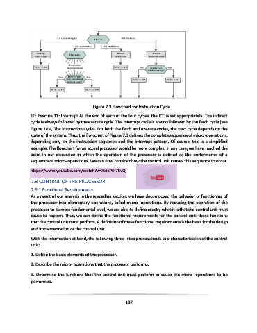
Figure 7.3 Flowchart for Instruction Cycle

               10: Execute 11: Interrupt At the end of each of the four cycles, the ICC is set appropriately. The indirect
               cycle is always followed by the execute cycle. The interrupt cycle is always followed by the fetch cycle (see
               Figure 14.4, The Instruction Cycle). For both the fetch and execute cycles, the next cycle depends on the
               state of the system. Thus, the flowchart of Figure 7.3 defines the complete sequence of micro -operations,
               depending only on the instruction sequence and the interrupt pattern. Of course, this is a simplified
               example. The flowchart for an actual processor would be more complex. In any case, we have reached the
               point  in  our  discussion  in  which  the  operation  of  the  processor  is  defined  as  the  performance  of  a
               sequence of micro- operations. We can now consider how the control unit causes this sequence to occur.

               https://www.youtube.com/watch?v=7tdkPEf75vQ

               7.3 CONTROL OF THE PROCESSOR

               7.3.1 Functional Requirements
               As a result of our analysis in the preceding section, we have decomposed the behavior or functioning of
               the processor into elementary operations, called micro- operations. By reducing the operation of the
               processor to its most fundamental level, we are able to define exactly what it is that the control unit must
               cause to happen. Thus, we can define the functional requirements for the control unit: those functions
               that the control unit must perform. A definition of these functional requirements is the basis for the design
               and implementation of the control unit.

               With the information at hand, the following three- step process leads to a characterization of the control
               unit:

               1. Define the basic elements of the processor.

               2. Describe the micro- operations that the processor performs.

               3. Determine the functions that the control unit must perform to cause the micro- operations to be
               performed.


                                                             187