
Page 182 - Handout of Computer Architecture (1)..
P. 182
involves a series of steps, each of which involves the processor registers. We will refer to these steps as
micro- operations. The prefix micro refers to the fact that each step is very simple and accomplishes very
little. Figure 20.1 depicts the relationship among the various concepts we have been discussing. To
summarize, the execution of a program consists of the sequential execution of instructions. Each
instruction is executed during an instruction cycle made up of shorter sub cycles (e.g., fetch, indirect,
execute, interrupt). The execution of each sub cycle involves one or more shorter operations, that is,
micro- operations. Micro- operations are the functional, or atomic, operations of a processor. In this
section, we will examine micro- operations to gain an understanding of how the events of any instruction
cycle can be described as a sequence of such micro- operations. A simple example will be used. In the
remainder of this chapter, we then show how the concept of micro- operations serves as a guide to the
design of the control unit.
https://www.youtube.com/watch?v=ScS-H92NHKE
7.2.1 The Fetch Cycle
We begin by looking at the fetch cycle, which occurs at the beginning of each instruction cycle and causes
an instruction to be fetched from memory. For purposes of discussion, we assume the organization
depicted in Figure 14.6 (Data Flow, Fetch Cycle). Four registers are involved:
■ Memory address register (MAR): Is connected to the address lines of the system bus. It specifies the
address in memory for a read or write operation.
■ Memory buffer register (MBR): Is connected to the data lines of the system bus. It contains the value to
be stored in memory or the last value read from memory.
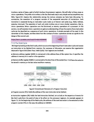
Figure7.1Constituent Elements of a Program Execution
■ Program counter (PC): Holds the address of the next instruction to be fetched.
■ Instruction registers (IR): Holds the last instruction fetched. Let us look at the sequence of events for
the fetch cycle from the point of view of its effect on the processor registers. An example appears in
Figure 7.2. At the beginning of the fetch cycle, the address of the next instruction to be executed is in the
program counter (PC); in this case, the address is 1100100.
182