
Page 189 - Handout of Computer Architecture (1)..
P. 189
We defer a discussion of the internal operation of the control unit to Section .3. The remainder of this
section is concerned with the interaction between the control unit and the other elements of the
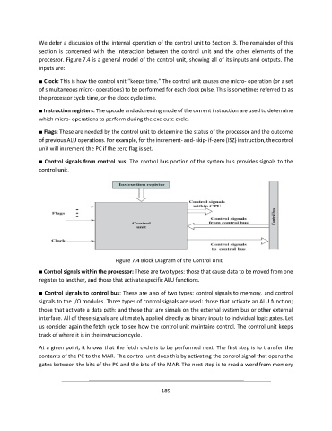
processor. Figure 7.4 is a general model of the control unit, showing all of its inputs and outputs. The
inputs are:
■ Clock: This is how the control unit “keeps time.” The control unit causes one micro- operation (or a set
of simultaneous micro- operations) to be performed for each clock pulse. This is sometimes referred to as
the processor cycle time, or the clock cycle time.
■ Instruction registers: The opcode and addressing mode of the current instruction are used to determine
which micro- operations to perform during the exe cute cycle.
■ Flags: These are needed by the control unit to determine the status of the processor and the outcome
of previous ALU operations. For example, for the increment- and- skip- if- zero (ISZ) instruction, the control
unit will increment the PC if the zero flag is set.
■ Control signals from control bus: The control bus portion of the system bus provides signals to the
control unit.
Figure 7.4 Block Diagram of the Control Unit
■ Control signals within the processor: These are two types: those that cause data to be moved from one
register to another, and those that activate specific ALU functions.
■ Control signals to control bus: These are also of two types: control signals to memory, and control
signals to the I/O modules. Three types of control signals are used: those that activate an ALU function;
those that activate a data path; and those that are signals on the external system bus or other external
interface. All of these signals are ultimately applied directly as binary inputs to individual logic gates. Let
us consider again the fetch cycle to see how the control unit maintains control. The control unit keeps
track of where it is in the instruction cycle.
At a given point, it knows that the fetch cycle is to be performed next. The first step is to transfer the
contents of the PC to the MAR. The control unit does this by activating the control signal that opens the
gates between the bits of the PC and the bits of the MAR. The next step is to read a word from memory
189