
Page 74 - Handout of Computer Architecture (1)..
P. 74
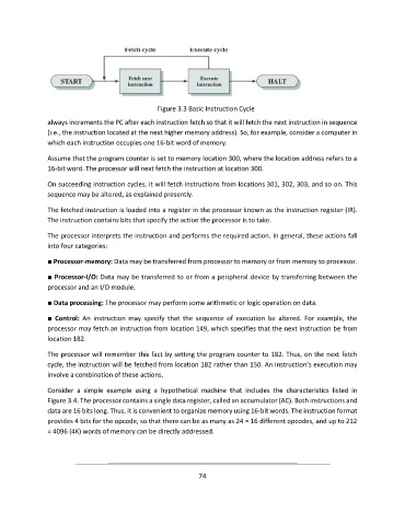
Figure 3.3 Basic Instruction Cycle
               always increments the PC after each instruction fetch so that it will fetch the next instruction in sequence
               (i.e., the instruction located at the next higher memory address). So, for example, consider a computer in
               which each instruction occupies one 16-bit word of memory.

               Assume that the program counter is set to memory location 300, where the location address refers to a
               16-bit word. The processor will next fetch the instruction at location 300.

               On succeeding instruction cycles, it will fetch instructions from locations 301, 302, 303, and so on. This
               sequence may be altered, as explained presently.

               The fetched instruction is loaded into a register in the processor known as the instruction register (IR).
               The instruction contains bits that specify the action the processor is to take.

               The processor interprets the instruction and performs the required action. In general, these actions fall
               into four categories:

               ■ Processor-memory: Data may be transferred from processor to memory or from memory to processor.

               ■ Processor-I/O: Data may be transferred to or from a peripheral device by transferring between the
               processor and an I/O module.
               ■ Data processing: The processor may perform some arithmetic or logic operation on data.

               ■  Control:  An  instruction  may  specify  that  the  sequence  of  execution  be  altered.  For  example,  the
               processor may fetch an instruction from location 149, which specifies that the next instruction be from
               location 182.

               The processor will remember this fact by setting the program counter to 182. Thus, on the next fetch
               cycle, the instruction will be fetched from location 182 rather than 150. An instruction’s execution may
               involve a combination of these actions.

               Consider  a  simple  example  using  a  hypothetical  machine  that  includes  the  characteristics  listed  in
               Figure 3.4. The processor contains a single data register, called an accumulator (AC). Both instructions and
               data are 16 bits long. Thus, it is convenient to organize memory using 16-bit words. The instruction format
               provides 4 bits for the opcode, so that there can be as many as 24 = 16 different opcodes, and up to 212
               = 4096 (4K) words of memory can be directly addressed.


                                                             74