
Page 75 - Handout of Computer Architecture (1)..
P. 75
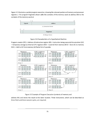
Figure 3.5 illustrates a partial program execution, showing the relevant portions of memory and processor
               registers.1 The program fragment shown adds the contents of the memory word at address 940 to the
               contents of the memory word at


                                        Figure 3.4 Characteristics of a Hypothetical Machine

               Program counter (PC) = Address of instruction register (IR) = Instruction being executed Accumulator (AC)
               = Temporary storage (c) Internal CPU registers 0001 = Load AC from memory 0010 = Store AC to memory
               0101 = Add to AC from memory (d) Partial list of opcodes


                                 Figure 3.5 Example of Program Execution (contents of memory and
               address 941 and stores the result in the latter location. Three instructions, which can be described as
               three fetch and three execute cycles, are required:


                                                             75