
Page 77 - Handout of Computer Architecture (1)..
P. 77
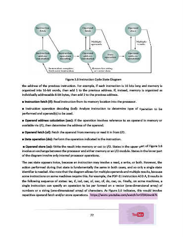
Figure 3.6 Instruction Cycle State Diagram
               the address of the previous instruction. For example, if each instruction is 16 bits long and memory is
               organized into 16-bit words, then add 1 to the previous address. If, instead, memory is organized as
               individually addressable 8-bit bytes, then add 2 to the previous address.

               ■ Instruction fetch (if): Read instruction from its memory location into the processor.

               ■  Instruction  operation  decoding  (iod):  Analyze  instruction  to  determine  type  of  operation  to  be
               performed and operand(s) to be used.

               ■ Operand address calculation (oac): If the operation involves reference to an operand in memory or
               available via I/O, then determine the address of the operand.

               ■ Operand fetch (of): Fetch the operand from memory or read it in from I/O.

               ■ Data operation (do): Perform the operation indicated in the instruction.
                ■ Operand store (os): Write the result into memory or out to I/O. States in the upper part of Figure 3.6
               involve an exchange between the processor and either memory or an I/O module. States in the lower part
               of the diagram involve only internal processor operations.

               The oac state appears twice, because an instruction may involve a read, a write, or both. However, the
               action performed during that state is fundamentally the same in both cases, and so only a single state
               identifier is needed. Also note that the diagram allows for multiple operands and multiple results, because
               some instructions on some machines require this. For example, the PDP-11 instruction ADD A, B results in
               the following sequence of states: iac, if, iod, oac, of, oac, of, do, oac, os. Finally, on some machines, a
               single  instruction  can  specify  an  operation  to  be  per  formed  on  a  vector  (one-dimensional  array)  of
               numbers or a string (one-dimensional array) of characters. As Figure 3.6 indicates, this would involve

               repetitive operand fetch and/or store operations.  https://www.youtube.com/watch?v=5f3NJnvnk7k


                                                             77