
Page 75 - UL_Report On_Part 1
P. 75
65 IITGN-UL/Façade 66 IITGN-UL/Façade
B D
2 2 # R 5 8 2 2 # R 5 9
2 2 # T R1 2 2 # T L1
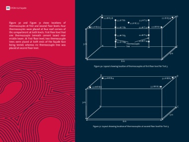
(iii) Test 3: Standard glass + MDF assembly Figure 30 and Figure 31 show locations of 2 2 # R 7 7
thermocouples at first and second floor levels. Four 2 2 # R 6 0 2 2 # T R2 2 2 # T L2 2 2 # R 6 1
This test was performed to study the behavior of assembly of thermocouples were placed at four roof corners of
glass panel with another commonly associated cladding the compartment at both levels. First floor level had
material i.e. Medium Density Fiberboard (MDF). The B D one thermocouple beneath cement board near 2 2 # T R3 2 2 # T L3
performance of façade system of toughened glass and MDF 1 2 # R 2 4 1 2 # R 3 1 2 # R 2 5 middle beam. At first floor level, two thermocouple
was studied by mounting the whole assembly over the full trees were placed at both ends of the façade face 2 2 # T R4 2 2 # T L4
height of test facility through aluminium cladding framework. 1 2 # R 7 4 being tested, whereas no thermocouple tree was 3 m A Thermocouple C
tree
Construction details of the test are similar to that of Test 2. 1 2 # R 2 6 1 2 # R 2 7 placed at second floor level.
Saint Gobain toughened glass of 1200 x 400 mm size and 6 1 2 # T 1
mm thickness was used. MDF panels of 6mm thickness with 3 m
exposed side painted with oil paint color were used. 60% Glass 1 2 # T 2
and 40% MDF was used. Aluminium cladding framework, fire Thermocouple 6 m
stop material and installation of MDF and glass panels on the 3 m 1 2 # 2 9 tree
cladding are similar to Test 2. A 1 2 # T 3 C Figure 30: Layout showing location of thermocouples at first floor level for Test 3
(a) Instrumentation 1 2 # B 3 1 2 # B 9 4 1 2 # B 4
The test compartment at all three levels was instrumented 1 2 # T 4 B
with K-type thermocouples (TC), strain gauges, LVDT, video and 1 2 # B 4 8 3 m 3 2 # R 8 4 3 2 # R 8 5 D
thermal imaging cameras. Specifications of instrumentation 1 2 # B 7 1 2 # B 100
used is similar to that used for Test 1. 6 m
Ground floor level was instrumented with 14 thermocouples Figure 29: Layout showing location of thermocouples at ground floor level for Test 3 3 2 # R 8 6 3 2 # R 8 7
and one thermocouple tree placed at center of the partition
wall to measure temperature profile across the height. One
thermocouple was placed at beam level beneath cement
board to determine effectiveness of cement board in providing
fire protection. Another thermocouple was placed at mid 3 m
height of partition wall where out of plane displacement of A C
masonry wall was attempted to measure by placing LVDT on
opposite side of the wall. Figure 29 shows the locations of the
thermocouples at ground floor level within the compartment 3 m
along with thermocouple tree. ABCD represents façade face
being tested of compartment 2. Nomenclature for 6 m
thermocouples is done in similar fashion as in Tests 1 and 2.
Figure 31: Layout showing location of thermocouples at second floor level for Test 3