
Page 121 - Med Plaza and Cancer Center
P. 121
"Oil-Less” Medical Air Medical Systems
2.0 Installation (continued)
2.5 Piping (continued)
2.5.1 Intake Piping (continued)
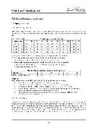
After determining the total system inlet air pipe size, the next step is to calculate the individual lines to each
compressor (for modular and larger tank mount systems only.) Use the table below to determine the inlet pipe
size.
LifeLine Intake Module Pipe Length (ft) - See Notes
Modules Size 10 20 30 40 50 60 80 100 120 140 160
7.5 HP 1.25 1.50 1.50 1.50 2.00 2.00 2.00 2.00 2.00 2.50 2.50 2.50
10 HP 1.25 1.50 1.50 2.00 2.00 2.00 2.00 2.00 2.50 2.50 2.50 2.50
15 HP 1.50 1.50 2.00 2.00 2.00 2.50 2.50 2.50 2.50 3.00 3.00 3.00
20 HP 1.50 2.00 2.00 2.50 2.50 2.50 3.00 3.00 3.00 3.00 3.50 3.50
1) All pipe sizes are based on the following: copper pipe (Type L), 14.7 psia, 70 deg F.
2) The minimum pipe size must be maintained for the total length of the inlet pipe.
Use next larger size pipe in the event the minimum size is not available.
3) When determining the total pipe length, add all the straight lengths of pipe together in
addition to the number of elbows times the effective pipe length for that pipe size.
(See the table and example below).
Effective Pipe Length Equivalent to each 90 deg Elbow
Pipe Size (in.) 1.50 2.00 2.50 3.00 3.50
Effective Pipe Length (ft) 3.7 5.1 5.4 5.9 6.6
Example:
Select the pipe size for a 10 HP Module with 20 feet of straight pipe and two elbows:
A) Select the pipe size of 1.5" diameter for 20 feet of straight pipe.
B) Determine the eff. pipe length for an elbow of 1.5" dia. (EPL = 3.7 ft / elbow).
C) Calculate the MODULE PIPE LENGTH {MPL (1.5" D) = 20 + (2 x 3.7) = 27.4 ft}
D) Check this MODULE PIPE LENGTH to see if it exceeds the minimum pipe size. In this case it
does, select the next larger pipe size from the table (D = 2.0").
E) To double check the pipe size, recalculate the MPL with the new diameter. MPL (D = 2.0") =
20 + (2 x 5.1) = 30.2 ft, which is okay.
2.5.2 Discharge Piping
For tankmount models, the discharge piping should be a minimum of ½” for 1-5 hp and 1” for 7.5-20 hp. For
compressor modules, the discharge piping to the control/dryer module should be a minimum of ¾” for 7.5-10 hp
and 1” for 15-20 hp. For modular systems, the receiver bypass piping should be ¾” for Duplex 7.5/10 hp, 1” for
Duplex 15/20 hp, 1” for Triplex 7.5/10 hp, 1” for Quadruplex 7.5 hp, 1-1/4” for Triplex 15/20 hp, 1-1/4” for
Quadruplex 15/20 hp, 1-1/2” for Quadruplex 20 hp. In all modular and SPC systems, the discharge piping out to
the hospital should correspond to a minimum of the sizes listed above for the system receiver bypass.
2-4