Page 533 - Med Plaza and Cancer Center
P. 533

Rough-In Installation


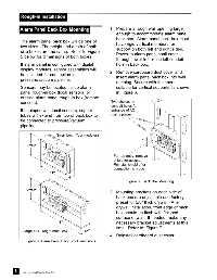
            Alarm Panel Back Box Mounting                      1. Prepare a rough wall opening large
                                                                   enough to accommodate alarm panel
                                                                   back box.  Alarm panel back box must
             The alarm panel back box will be one of
                                                                   have rigid vertical members for
             two sizes.  The height and depth of both
                                                                   support on both left and right sides.
             size boxes are the same.  Refer to Figure             Power to alarm panel shall enter
             5 below for dimensions of both boxes.
                                                                   through lower left or top left conduit
             If alarm panel is configured with digital             hole in back box.
             display modules, sensor assemblies will
                                                               2. Remove cardboard dust cover and
             be included for connection to
                                                                   insert alarm panel back box into wall
             pressure/vacuum pipeline.
                                                                   opening. Secure with fasteners
             Sensors may be located inside alarm                   suitable for vertical supports as shown
             panel rough-in box (local sensors) or                 in Figure 6.
             outside alarm panel rough-in box (remote
             sensors).                                          Two choices of
                                                                conduit holes for
             If equipped with local sensors, copper             entrance of AC
             tubes will extend from top of back box to          mains power
             be connected to pressure/vacuum                                   top entry
             pipeline.                                                        side entry

                                 Small box - (four modules)


                                                                 For top entry, remove
                                                                 shield for access.
                                                                 Reinstall shield after
                                                                 connection is made


                                                                        Figure 6:  Back Box Mounting

                                                               3. Mounting brackets on each side of
                                                                   back box are adjustable and factory
                                                                   preset for 5/8” thick drywall.  After
                                                                   drywall installation, front edge of back
                                                                   box should be flush with finished
                                                                   surface of wall.  If needed, make any
                                                                   necessary bracket adjustments at this
                                                                   time.  Refer to  Figure 7.
              Large box - (eight modules)
                                                               4. Reinstall cardboard dust cover.
               Figure 5: Alarm Panel Back Box Dimensions


         8
              Part No. 6-847684-00 Rev. E00
   528   529   530   531   532   533   534   535   536   537   538