
Page 536 - Med Plaza and Cancer Center
P. 536
Wiring Installation
General Requirements Wire Routing
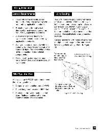
• Power all alarms from life safety Two 7/8” holes are provided for entrance
branch of emergency power system as of AC mains power. One hole on lower
required by applicable standards. left side and one hole on top left of alarm
panel back box. NO OTHER HOLES
• Protect all wiring from physical
SHOULD BE PUNCHED OR USED. If
damage by raceways or conduit as hole on top left is used, remove shield for
required by applicable standards.
access. Reinstall shield after connection
• Wire master panels directly to is made.
switches or sensors as required by
Several additional 7/8” holes are provided
applicable standards.
on right side of top panel for entrance of
• Wiring runs should be made with color low voltage field wiring. Refer to Figure
coded wire. Record color, signal, and 11.
source of signal for each wiring lead to
aid in connection of alarm finish
Two choices of
components. Holes for entrance of
conduit holes for
low voltage field wiring
• Avoid installing alarm panels near entrance of AC
mains power
radio transmitters, electrical motors, or
switchgear. side entry
top entry
Wire Type And Size
All low voltage MEGA2 wiring must meet
the following criteria:
For top entry, remove
• Copper wire no smaller than 22 AWG. shield for access. Reinstall
shield after connection is
• Circuit length not to exceed 5000 feet.
made
• Cable must be twisted pair shielded Figure 11: Wire Routing
type. Multi-pair cables within one
common shield are acceptable.
11
Part No. 6-847684-00 Rev. E00