Page 534 - Med Plaza and Cancer Center
P. 534

Rough-In Installation


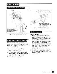
                Alarm Panel Back Box Mounting


                                                                                   Four holes in back of box are
                                                                                   provided for surface mounting


                                                                                     Rear conduit knockouts
                                                                                     (either side) are recommend-
                                                                                     ed for  sensor wiring

                                                                         Figure 8: Remote Sensor Back Box
                 Loosen screws to
                 adjust back box depth
                 (same each side)
                                                                   Pipeline Connection

                     Figure 7: Mounting Bracket Adjustment
                                                                   Sensor Module
                                                                   1. Braze copper extension tubes from
                                                                      sensor rough-in to appropriate
                                                                      pressure/vacuum piping system drops
                                                                      as shown in Figure 9.  Braze
                Remote Sensor Back Box Mounting
                                                                      connections per procedures required
                Alarm panels ordered with remote                      by NFPA 99 or CAN/CSA-Z305.1.
                sensors are provided with separate metal              Use appropriate measures to prevent
                boxes for each sensor.  Mount each                    overheating and damage to internal
                sensor box as follows:                                components of sensor rough-in
                                                                      assemblies.
                1. Remove sensor rough-in from
                    mounting box (Figure 8).                       2. Perform standing pressure tests and
                                                                      cross connection tests as required by
                2. Using four mounting holes provided,                NFPA and CSA.
                    attach box to a wall or other structural
                    support.  (fasteners by others).
                3. Reinstall sensor rough-in.


                                                                                                                  9
                                                                                            Part No. 6-847684-00 Rev. E00
   529   530   531   532   533   534   535   536   537   538   539