
Page 864 - Med Plaza and Cancer Center
P. 864
PROPRIETARY AND CONFIDENTIAL DRAFT 28/Feb/03
4.24 Local-Mount Transducer
Chapter 4: Removal, Replacement, and Adjustment Procedures
a. Disconnect the two flag terminals (C) supplying power to the Area
Alarm Breakout P.C. Board (D).
b. Remove and save the two screws (E) securing the power supply
assembly (B) to the mounting bracket (F).
c. Without putting excessive strain on the input power wiring (G) or the
ground wire (H), set the power supply assembly (B) to the side.
d. Remove and save the two screws (I) securing the mounting bracket (F)
to the rough-in box (J).
e. Remove and save the mounting bracket (F).
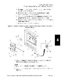
Figure 4-25. Transducer Assembly (Area Line Pressure Alarm (P0321) from Hill-Rom or
Medaes is Shown)
4
5. Note the position of the green wire (or shield wire) (K) in the terminal
block (L) located inside the transducer (A).
NOTE:
Polarity does not need to be observed for the red and black wires.
6. Loosen the screws (M) securing the three wires (K and N) to the terminal
block (L).
MedPlus TotalAlert™ Alarm Network Operation and Maintenance Manual (man291ra) Page 4 - 65