
Page 240 - Womens Pavilion
P. 240
“Oil-Less” Scroll Medical Air
Appendix D: TotalAlert Embedded Control System
D.2.6 5.7” Dryer Screen (If Equipped) D.2.7 5.7” Service Screen
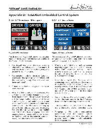
Figure D.8 Dryer Screen Figure D.9 Service Screen
The dryer screen (Figure D.8) shows the operation The service screen (Figure D.9) allows the selection
mode of the dryer(s) and which tower is online if of various sub screens along with the current
the “Status” mode is selected: ambient temperature at the system:
• The default view when the dryer screen is • Maintenance – Additional multiple screens
selected shows both dryer operation modes. If depicting suggested and required maintenance
only one dryer is installed on the system, only items with resettable timers. When
the left “Dryer 1” is visible. maintenance is due, both the maintenance
button and the service icon on the tool bar
• The operation modes for the dryer: Automatic turn red instead of blue.
(Green and dew point purge controlled), Off
(Red and not running), Manual (Green and • Diagnostic - Depicts the I/O status of the
timer controlled). connecting unit controller board. For example,
the digital inputs (X1-X7 as 0 or 1), the analog
• If there are no dryers on the system, this screen readings (T1-T2, I1-I4, P1-P2 and V1-V2 with
is not available. A/D values), the 24VDC powered digital
outputs (Z1-Z2 as 0 or 1) and the dry contacts
• When the Status button “i” is selected, the (Y1-Y12 as 0 or 1).
view on the dryer section changes to an image
depicting the dryer. The arrows on the tower • Version – Displays the RS485 communication
and the purge muffl er indicate which tower version, fi rmware versions for the 5.7 display
is online (green arrow pointing down) and board and the connecting controller board.
which tower is offl ine (no arrow or blue arrow
pointing up). The blue arrow pointing up • Testing – Allows for test mode of all alarm
on the tower indicates that tower is purging. events. See Section D.5 for more information.
The two blue arrows on the purge muffl er
also indicate the dryer is purging. Once the • Temperatures – Display the current ambient
purge cycle is complete and the dryer is ready temperature and the current cabinet
to switch (based on dewpoint in automatic temperature (optional). When the button is
mode), the blue arrows are not visible. pressed, the trend information is available for
these temperatures.
D-5 4107 9000 69.06