
Page 243 - Womens Pavilion
P. 243
“Oil-Less” Scroll Medical Air
Appendix D: TotalAlert Embedded Control System
D.2.12 5.7” Settings Screen D.3 PCB2 (3.5” Display Controller)
D.3.1 Basic Software Architecture
The primary purpose of PCB2 is to drive the LCD
display for the 3.5” Unit screen. Its other functions
include the following.
1. Communicate to the Pump Controller Board
(PCB4) via a RS-485 bus to relay commands
from the touch screen interface and display
messages from the pump controller.
2. Interface to the 3.5” Display touch screen to
interpret the user interaction.
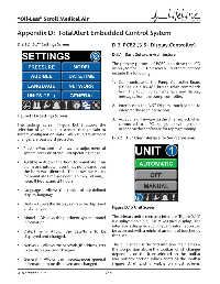
Figure D.14 Settings Screen
3. Accept new fi rmware via the Ethernet jack when
The settings screen (Figure D.14) allows the connected to a PC confi gured with genuine
selection of various sub screens that pertain to BeaconMedaes software for reprogramming.
system confi guration data. All value/adjustment
changes are password protected. D.3.2 3.5” User Interface for Source Systems
• Pressure/Vacuum – Allows the adjustment of
system pressure or vacuum operating range.
• Audible – Allows the horn to re-initiate if an
alarm or shutdown event has not cleared, but
the horn was silenced. The allowable values
for re-initiate time are never, 15 min, 30 min, 1
hour, 8 hours, and 24 hours.
• Language – Allows the choice of pre-defi ned
display language.
• Units – Allows the display units to be displayed
and changed. Figure D.15 Unit Screen
• Model – Displays the pertinent system model The primary unit screen user interface (Figure D.15)
information. is displayed on a 3.5” 240 x 320 pixel display. The
interface is designed such that any information can
• Date/Time – Allows the date/time to be be accessed with a minimal amount of touches by
displayed and changed. the user.
• Network – Allows the network (IP address, etc) The 3.5” screen is divided into two main areas –
to be displayed and changed. the top portion above the toolbar which changes
depending on the icon selected on the toolbar
• General – Allows the miscellaneous general and bottom portion which contains the toolbar
information to be displayed and changed. (Figure D.16) and is visible on most screens.
4107 9000 69.06 D-8