
Page 246 - Womens Pavilion
P. 246
“Oil-Less” Scroll Medical Air
Appendix D: TotalAlert Embedded Control System
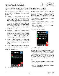
The service screen (Figure D.21) allows access The alarms screen (Figure D.22) shows all of the
to the unit “jog” feature, diagnostic screen and unit alarm information. An alarm is classifi ed as
version screen: an event of signifi cance that does not shut the
unit down. These alarms are latched and are not
• Rotation – Allows the unit to run for a short cleared until a user presses the reset button on
period to check rotation. When pressed, the the alarms screen. This reset button will reset all
unit will either begin the “jog” sequence or alarms for that given unit.
show a screen instructing you to place the
unit in “OFF” mode fi rst (the unit must be • Green alarm condition indicates a normal
in “OFF” mode before it can check rotation). status for that condition.
When “jog” mode is started, the unit will fi rst
delay for 5 seconds to allow the user to get in • Red alarm condition indicates an abnormal
position to check the rotation, then run the status for that condition.
unit for a brief period.
D.3.9 3.5” Shutdown Screen
• Diagnostic – Depicts the I/O status of the
connecting unit controller board. For example,
the digital inputs (X1-X4 as 0 or 1), the analog
readings (T1-T3 and I1 with A/D values), the
24VDC powered digital outputs (Z1-Z5 as 0 or
1) and the dry contacts (Y1-Y3 as 0 or 1).
• Version – Displays the RS485 communication
version, the fi rmware versions for the 3.5
display board and the connecting controller
board.
• Testing – Allows for test mode of all shutdown
events. See Section D.5 for more information.
Figure D.23 3.5” Shutdown Screen
D.3.8 3.5” Alarms Screen
The shutdown screen (Figure D.23) shows all of
the unit shutdown event information. A shutdown
is classifi ed as an event of signifi cance that does
shut the unit down. These shutdown events are
latched and are not cleared until a user presses
the reset button on the shutdown screen. This
reset button will reset all shutdown events for that
given unit.
• Green shutdown condition indicates a normal
status for that condition.
• Red alarm shutdown indicates an abnormal
status for that condition.
Figure D.22 3.5” Alarms Screen
D-11 4107 9000 69.06