
Page 244 - Womens Pavilion
P. 244
“Oil-Less” Scroll Medical Air
Appendix D: TotalAlert Embedded Control System
• If the connecting board is incompatible with
the display board (for example, the boards
are not properly connected), only the bottom
Figure D.16 3.5” Screen Toolbar version button appears with a red button
background.
From left to right, the toolbar icons represent the
following: D.3.4 3.5” Main Screen
Main Screen (default)
Status/Information (Hourmeter)
Service
Alarms (no Shutdown)
Shutdown
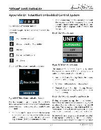
Figure D.18 3.5” Main Screen
D.3.3 3.5” Boot/Communication Screen
The main (default) screen (Figure D.18) shows
the operation mode of the unit along with its
automatic versus manual mode setting:
• Automatic (Blue = Standby, Grey = Unselected,
Green = Unit Running)
• Off (Red = Selected, Grey = Unselected)
• Manual (Blue = Standby – Backup Pressure
Switch is not closed, Grey = Unselected, Green
= Unit Running)
D.3.5 3.5” Main Screen: Manual Override
Figure D.17 Boot/Communication Screen
During the system startup, the manual override,
The boot/communication screen (Figure D.17) located on the printed circuit board (PCB4), switch
shows at boot time and changes to the default main is utilized to ensure the compressor is in the Off
screen once communication and compatibility are position. The manual override switch on PCB4 is a
confi rmed: safety measure as well, for emergency situations to
ensure the compressor unit produces medical air.
• If a RS485 link failure is detected the link icon
at the top of the screen appears and the version In the event of an emergency and the control system
button appears to allow the user to check is not operating eff ectively, the manual override
display board (PCB2) version information. switch can be moved from the Automatic position
D-9 4107 9000 69.06