
Page 311 - Womens Pavilion
P. 311
Oil-Less Claw Medical Vacuum
Appendix A: TotalAlert Embedded Control System
A.7 Remote Monitoring
CAUTION: The information systems personnel
should be notifi ed before changing any of the
network settings. Changing the settings could
keep the equipment from working properly.
A.7.1 Set Up: Equipment Required
• PC with an Ethernet connection
• PC with a web browser, such as Microsoft
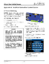
Internet Explorer Customer Ethernet Connection
on PCB3 Master
• Cat5 or better Ethernet cable
Figure A.26 Connecting the cable
A.7.2 Set Up: Physical Connection
1. Using a Cat5 Ethernet cable, connect the
WARNING: medical vacuum system to an Ethernet switch
or hub. Connect the cable to the Customer
ONLY CONNECT THE CUSTOMER
NETWORK TO THE CUSTOMER Ethernet Connection (Figure A.26) on PCB3
ETHERNET CONNECTION AS SHOWN Master board.
IN FIGURE A.26.
2. Verify the green LINK LED on the printed circuit
board illuminates.
DO NOT UNPLUG EXISTING ETHERNET
CABLES USED FOR THE INTERNAL A.7.3 Set Up: Network Confi guration
CONNECTIONS. DO NOT ATTEMPT
TO REMOVE ETHERNET SECURITY
PROTECTORS TO USE FOR CUSTOMER
ETHERNET CONNECTION.
IF THE CUSTOMER ETHERNET IS
PLACED IN AN INTERNAL ETHERNET
CONNECTION, THE INTERNAL
ETHERNET FUNCTIONALITY WILL NOT
PERFORM AS DESIGNED.
(Network screen is found in Settings section from
Main toolbar)
Figure A.27 System IP Address
4107 9000 95.04 A-14