
Page 307 - Womens Pavilion
P. 307
Oil-Less Claw Medical Vacuum
Appendix A: TotalAlert Embedded Control System
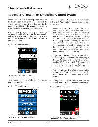
If the switch is in Manual or Off postion on PCB4, The service screen (Figure A.20) allows access
the touchscreen controls no longer control the to the unit “jog” feature, diagnostic screen and
vacuum pump. Moving the switch back to the version screen:
Automatic position puts the unit under the control
of the TotalAlert Embedded control system. • Rotation – Allows the unit to run for a short
period to check rotation. When pressed, the
CAUTION: The “Manual Override” mode of unit will either begin the “jog” sequence or
operation should only be used for emergencies show a screen instructing you to place the
such as a loss of unit display board or loss of unit in “OFF” mode fi rst (the unit must be
display touchscreen and should not be used for in “OFF” mode before it can check rotation).
normal operation. When “jog” mode is started, the unit will
fi rst delay for 5 seconds to allow the user to
A.3.6 3.5” Status Screen get in position to check the rotation, then run
the unit for a brief period. For VSD systems,
rotation must also be checked in “Automatic”
mode. See Section 3.0 for details.
• Diagnostic – Depicts the I/O status of the
connecting unit controller board. For example,
the digital inputs (X1-X4 as 0 or 1), the analog
readings (T1-T3 and I1 with A/D values), the
24VDC powered digital outputs (Z1-Z5 as 0 or
1) and the dry contacts (Y1-Y3 as 0 or 1).
• Version – Displays the RS485 communication
version, the fi rmware versions for the 3.5
display board and the connecting controller
Figure A.19 3.5” Status Screen board.
The status screen (Figure A.19) shows the running • Testing – Allows for test mode of all shutdown
hour meter values.
events. See Section A.5 for more information.
A.3.7 3.5” Service Screen A.3.8 3.5” Alarms Screen
Figure A.20 3.5” Service Screen Figure A.21 3.5” Alarms Screen
4107 9000 95.04 A-10