
Page 303 - Womens Pavilion
P. 303
Oil-Less Claw Medical Vacuum
Appendix A: TotalAlert Embedded Control System
The maintenance screens (Figure A.9) are accessed • Green alarm condition indicates a normal
via the service screen: status for that condition.
• Additional multiple screens depicting • Red alarm condition indicates an abnormal
suggested and required maintenance items status for that condition.
with resettable timers. If an item is past due
the button color changes from blue to red if • The horn silence button at the bottom right
the item is a required maintenance versus a will show Red if the horn is on and not reset
suggested maintenance. yet. Once the horn is silenced, the button will
return back to the gray condition.
• The fi rst (default) screen shows as the System
maintenance. Items that are suggested are A.2.9 5.7” Shutdown Screen
shown as a grey button and indicators are not
visible or fl agged for these items. When the
user resets the timer, the action is logged in the
service history.
• Other screens (Unit and History) are accessed
by pressing the bottom round icons. Note
that only unit icons are shown if the unit is
physically installed and not an expansion unit.
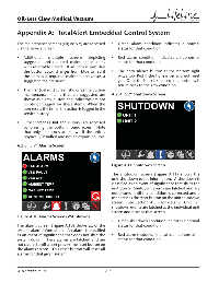
A.2.8 5.7” Alarms Screen
Figure A.11 Shutdown Screen
The shutdown screen (Figure A.11) shows the
unit shutdown event information. A shutdown is
classifi ed as an event of signifi cance that shuts the
unit down. Shutdown events are latched and are
not cleared until the condition is corrected and a
user presses the reset button on the unit shutdown
screen. See Section A.3.9 for details. Unit “X”
shutdown events are latched at the individual unit
screen and reset at that screen.
Figure A.10 Alarms Screen (VSD shown)
• Green shutdown condition indicates a normal
The alarms screen (Figure A.10) shows all of the status for that condition.
system alarm information. An alarm is classifi ed
as an event of signifi cance that does not shut the • Red alarm shutdown indicates an abnormal
system down. These alarms are latched and are status for that condition.
not cleared until a user presses the reset button on
the alarms screen. This reset button will reset all
alarms for that given system.
4107 9000 95.04 A-6