
Page 300 - Womens Pavilion
P. 300
Oil-Less Claw Medical Vacuum
Appendix A: TotalAlert Embedded Control System
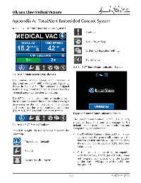
A.2.2 5.7” User Interface for Source Systems
Shutdown
Event History Log
System Confi guration Settings
Horn Silence
A.2.3 5.7” Boot/Communication Screen
Figure A.3 Main Screen (VSD shown)
The primary master screen user interface is
displayed on a 5.7” 640 x 480 pixel display as
shown in Figure A.3. The interface is designed
such that any information can be accessed with a
minimal amount of touches by the user.
The 5.7” screen is divided into two main areas –
the top portion above the toolbar which changes
depending on the icon selected on the toolbar
and bottom portion which contains the toolbar
(Figure A.4) and is available on most screens.
Figure A.5 Boot/Communication Screen
The boot/communication screen (Figure A.5)
shows at boot time and will change to the
Figure A.4 5.7” Screen Toolbar default main screen once communication and
compatibility are confi rmed:
From left to right, the toolbar icons represent the
following: • If a RS485 link failure is detected the link icon
at the top of the screen will appear and the
bottom version button will appear to allow
Main Screen (default)
the user to check display board (PCB1) version
information.
Service
• If the connecting board is incompatible
with the display board (for example, board
not properly connected), only the bottom
Alarms (no Shutdown)
version button will appear with a red button
background.
A-3 4107 9000 95.04