
Page 305 - Womens Pavilion
P. 305
Oil-Less Claw Medical Vacuum
Appendix A: TotalAlert Embedded Control System
A.3 PCB2 (3.5” Display Controller)
A.3.1 Basic Software Architecture
Figure A.15 3.5” Screen Toolbar
The primary purpose of PCB2 is to drive the LCD
display for the 3.5” Unit screen. Its other functions From left to right, the toolbar icons represent the
include the following. following:
1. Communicate to the Pump Controller Board
(PCB4) via a RS-485 bus to relay commands Main Screen (default)
from the touch screen interface and display
messages from the pump controller. Status/Information (Hourmeter)
2. Interface to the 3.5” Display touch screen to
interpret the user interaction. Service
3. Accept new fi rmware via the Ethernet jack when Alarms (no Shutdown)
connected to a PC confi gured with genuine
BeaconMedaes software for reprogramming.
Shutdown
A.3.2 3.5” User Interface for Source Systems
A.3.3 3.5” Boot/Communication Screen
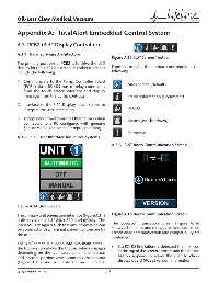
Figure A.14 Unit Screen
The primary unit screen user interface (Figure A.14) Figure A.16 Boot/Communication Screen
is displayed on a 3.5” 240 x 320 pixel display. The
interface is designed such that any information can The boot/communication screen (Figure A.16)
be accessed with a minimal amount of touches by shows at boot time and changes to the default main
the user. screen once communication and compatibility are
confi rmed:
The 3.5” screen is divided into two main areas –
the top portion above the toolbar which changes • If a RS485 link failure is detected the link icon
depending on the icon selected on the toolbar at the top of the screen appears and the version
and bottom portion which contains the toolbar button appears to allow the user to check
(Figure A.15) and is visible on most screens. display board (PCB2) version information.
4107 9000 95.04 A-8