
Page 299 - Womens Pavilion
P. 299
Oil-Less Claw Medical Vacuum
Appendix A: TotalAlert Embedded Control System
A.1 Board Confi gurations A.2 PCB1 (5.7” Display Controller)
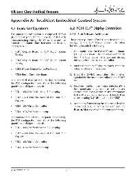
The source control system is comprised of four A.2.1 Basic Software Architecture
(4) diff erent printed circuit boards (PCBs) with
interconnecting wiring (RS485 or Ethernet) for The primary purpose of PCB1 is to drive the LCD
internal communications between the boards. display for the 5.7” Master screen. Its other
See Figure A.2. functions include the following:
1. PCB1: Display Board for 5.7” Touch Screen 1. Communicate to the Master Controller Board
Display (PCB3) via a RS-485 bus to relay commands
from the touch screen interface and display
2. PCB2: Display Board for 3.5” Touch Screen messages from the master controller.
Display
2. Interface to the 5.7” Display touch screen to
3. PCB3: Master Source Controller Board interpret the user interaction.
4. PCB4: Pump Controller Board 3. Drive the 24VDC local alarm horn when
signaled by the master controller via the RS485
In a standard medical vacuum duplex system, bus.
the PCB confi guration consists of the following
quantities and types of boards: 4. Read the input from the motion detector at the
front panel and relay the status to the master
• PCB1 – (1) One for the Main 5.7” display controller so it can distribute the information
to the other pump controllers and then to their
• PCB2 – (2) One for each of the Unit 3.5” corresponding 3.5” display boards (PCB2).
displays
5. Accept new fi rmware via the Ethernet jack when
• PCB3 – (1) Master Controller connected to a PC confi gured with genuine
BeaconMedæs software for reprogramming.
• PCB4 – (2) One for each pump
In a standard medical vacuum quadruplex system,
the PCB confi guration consists of the following
quantities and types of boards:
• PCB1 – (1) One for the Main 5.7” display
• PCB2 – (4) One for each of the Unit 3.5”
displays
• PCB3 – (1) Master Controller
• PCB4 – (4) One for each pump
4107 9000 95.04 A-2