
Page 364 - Womens Pavilion
P. 364
Steps to Re-Calibrate the Sensor from Area Module v4.0
1. Turn on Alarm
2. Set switches #8 & #10 the OFF position
3. Set switches #5 & #6 the ON position
4. The display will show the current reading of the pressure
5. Adjust the calibration, using the “UP” and “DOWN” push buttons, to the desired value.
6. Set switches #5 & #6 the OFF position
7. Turn on #10 if Aims is connected (do not turn on #8)
When you have completed step #7, the display module will automatically go into a “RESET” mode. This will store the
data that you had entered.
Area, 2 in 1, Compact Display Module
Alert - 2 Series
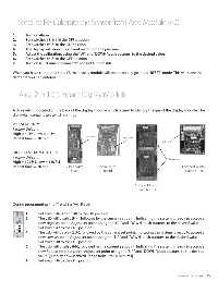
THE AREA/2 IN 1 DISPLAY MODULE
A dip-switch is located on the back of the display module which is used to identify the gas of the display module. The
A dip switch is located on the back of the display module
dip-switch contains ten switch settings.
which is used to identify the gas of the display module. The
dip-switch contains ten switch settings.
PRESSURE ONLY
Factory Default: 2 in 1 Alarm
PRESSURE ONLY Board
High = 60 Psi, Low = 40 Psi
Factory Default: Dip-Switch Dip-Switch
Repeat time = 30 min.
High = 60 Psi, Low = 40 Psi Dip-Switch
Repeat time = 30 min.
HIGH PRESSURE/NITROGEN
Factory Default:
HIGH PRESSURE/NITROGEN Dip-Switches
High = 195 Psi, Low = 140 Psi
Factory Default:
Repeat time = 30 min.
High = 195 Psi, Low = 140 Psi 2 in 1 Alarm Area Alarm Compact Alarm
Area Alarm
Board
Board
Board (v2.02)
Repeat time = 30 min. Board
During Programming the Compact Alarm
“Trend Bar” will Flash! Board (v2.01)
1. Set switch #6, #7 and #8 to the ON position.
2. During programming, the “Trend Bar” will Flash!
The LED will display (HI-HI- HI-HI- HI-), followed by the current set point.
Indicating the system is ready to accept a new High set point.
Adjust set point, using the “UP” and “DOWN” push buttons, to the
1.
Set switch #6, #7 and #8 to the ON position.
desired value.
The LED will display (HI-), followed by the current set point. Indicating the system is ready to accept a
2.
3. Set switch #7 to the OFF position.
new High set point. Adjust set point, using the “UP” and “DOWN” push buttons, to the desired value.
4. The LED will display (LO-LO-), followed by the current set point.
LO-
LO-
LO-
Set switch #7 to the OFF position.
3.
Indicating the system is ready to accept a new Low set point.
4.
The LED will display (LO-), followed by the current set point. Indicating the system is ready to accept a
Adjust set point, using the “UP” and “DOWN” push buttons, to the
new Low set point. Adjust set point, using the “UP” and “DOWN” push buttons, to the desired value.
desired value.
Set switch #8 to the OFF position.
5.
5. Set switch #8 to the OFF position.
The LED will display (I-I-), followed by the current set point. Indicating the system is ready to accept a
6.
6. The LED will display (I-I-I-I- I-I-I-I- I-I-), followed by the current set point.
new Repeat time set point. Adjust set point using the “UP” and “DOWN” push buttons, to the desired
Indicating the system is ready to accept a new Repeat time set
value. [(Display dd=Disabled) Range from 1 to 60 Minutes]
point. Adjust set point using the “UP” and “DOWN” push buttons,
to the desired value. [(Display dd=Disabled) Range from 1 to 60
7.
Set switch #6 to the OFF position.
Minutes]
7. Set switch #6 to the
OFF position.
www.amico.com 15
When you have completed
step #7, the display module
will automatically go into a
“RESET” mode. This will store
the data that you had entered.
Page: 17