
Page 16 - AAS & AES & FES 01082016_Neat
P. 16
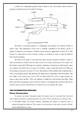
A sketch of a temperature-gradient lamp is shown in Fig. The element, whose emissive

               spectrum is desired, placed in the bulb of the lamp.


                       The  bulb  is  electrically  heated  to  a  temperature  that  produces  the  desired  amount  of

               atomic  vapor.  The  temperature  of  the  oven  is  carefully  controlled  by  the  electric  circuit.  A
               current is caused to flow between a filament and an anode by application of about 30 V. The

               filament is coated with an oxide of barium, calcium, or strontium in order to make the filament
               more electron-emitting.

                       The body of the lamp is constructed from glass but the transparent window is made of

               silica, by placing the window near the warm section of the lamp, condensation of hot vapor onto
               the window is prevented. The lamp also contains a relatively cool portion on which atomic vapor

               can condense and which serves to protect the window. Argon is generally used as the filler gas
               for the lamp at a pressure of about 1 to 5 torr. The intensity of the radiation that is emitted from a

               TGL is considerably greater than that from HC lamps and is comparable to that from EDLs. The

               line widths of the emitted lines from a TGL  are about 0.001 nm, which is approximately the
               same  as  those  from  an  EDL.  TGLs  are  claimed  to  exhibit less  self-reversal  than  EDLs.  Both

               EDLs and TGLs are primarily used in AAS for studies at wavelengths that are below 200 nm for
               elements such as arsenic and selenium for which there are no adequate HC lamps.


               THE ATOMIZATION PROCESS
               Flame Atomization

                       To measure an atomic absorption signal, the analyte must be converted from dissolved
               ions in aqueous solution to reduced gas phase free atoms. The overall process is outlined in Fig.

                 As  described  earlier,  the  sample  solution,  containing  the  analyte  as  dissolved  ions,  is

                   aspirated through the nebulizer. The solution is converted into a fine mist or aerosol, with the
                   analyte still dissolved as ions.

                                                                                                           15