
Page 655 - Chief Architect Reference Manual
P. 655
Creating Wiring Schematics
Creating Wiring Schematics
Electrical schematics can be created in two
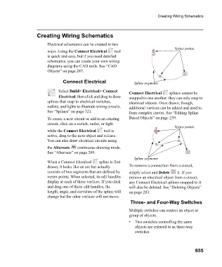
Vertex points
ways. Using the Connect Electrical tool
is quick and easy, but if you need detailed
schematics, you can create your own wiring
diagrams using the CAD tools. See “CAD
Objects” on page 287.
Connect Electrical Spline segments
Select Build> Electrical> Connect Connect Electrical splines cannot be
Electrical, then click and drag to draw snapped to one another: they can only snap to
splines that snap to electrical switches, electrical objects. Once drawn, though,
outlets, and lights to illustrate wiring circuits. additional vertices can be added and used to
See “Splines” on page 321. form complex curves. See “Editing Spline
To create a new circuit or add to an existing Based Objects” on page 239.
circuit, click on a switch, outlet, or light
Vertex points
while the Connect Electrical tool is
active, drag to the next object and release.
You can also draw electrical circuits using
the Alternate continuous drawing mode.
See “Alternate” on page 209.
Spline segments
When a Connect Electrical spline is first
drawn, it looks like an arc but actually To remove a connection from a circuit,
consists of two segments that are defined by simply select and Delete it. If you
vertex points. When selected, its edit handles remove an electrical object from a circuit,
display at each of these vertices. If you click any Connect Electrical splines snapped to it
and drag one of these edit handles, the will also be deleted. See “Deleting Objects”
length, angle, and curvature of the spline will on page 283.
change but the other vertices will not move.
Three- and Four-Way Switches
Multiple switches can control an object or
group of objects.
• Two switches controlling the same
objects are referred to as three-way
switches.
655