
Page 41 - Gyro Wrap™ Signature ® Series
P. 41
GYRO WRAP™ Signature ® Series
Installation
Utilities: Pneumatic, Water and Electrical
Pneumatic Connections
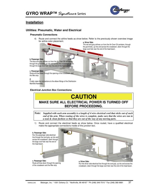
4) Route and connect the airline feeds as show below. Refer to the previously shown overview image
for airline color placement.
a. Driver Side:
The red and gray airlines run from the Air-Over-Oil canisters, through
the grommets, up into and across the crossbeam, down through the
large oval hole near the end of the head beam.
b. Passenger Side:
The blue and gray airlines run from the Air-Over-Oil canisters,
through the grommets, up into and across the crossbeam, down
through the large oval hole near the end of the head beam.
c. Passenger Side:
Route all lines down through the opening of the crossbeam and
the filler strip
d.
Finally make the connections to the elbow fittings of the Distribution
Manifold Assembly.
Electrical Junction Box Connections
CAUTION
MAKE SURE ALL ELECTRICAL POWER IS TURNED OFF
BEFORE PROCEEDING.
Note: Supplied with each arm assembly is a length of 4 wire electrical cord that sticks out of each
end of the arm. When routing of the wires is complete, make sure that the wires are ran in
a neat & clean fashion so that they are out of the way of any moving parts.
1) Route and connect the electrical feeds as show below. Once routed, have a qualified electrical
make the appropriate connections inside of the junction box.
b. Passenger Side:
Run the passenger side electrical
line through the cord grip, up into and
across the crossbeam, down through
the large oval hole near the end of
the head beam.
c. Passenger Side: a. Driver Side:
Route all lines down through the opening Run the driver side electrical line through the cord grip, up into and across the
of the crossbeam and the filler strip crossbeam, down through the large oval hole near the end of the head beam.
1MANUL248 Belanger, Inc. * 1001 Doheny Ct. * Northville, MI 48167 * Ph (248) 349-7010 * Fax (248) 380-9681 37