
Page 42 - Gyro Wrap™ Signature ® Series
P. 42
GYRO WRAP™ Signature ® Series
Installation
Utilities: Pneumatic, Water and Electrical
Electrical Junction Box Connections
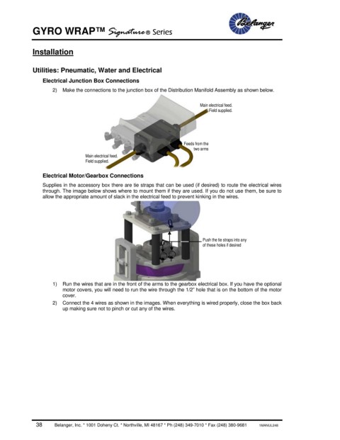
2) Make the connections to the junction box of the Distribution Manifold Assembly as shown below.
Main electrical feed.
Field supplied.
Feeds from the
two arms
Main electrical feed.
Field supplied.
Electrical Motor/Gearbox Connections
Supplies in the accessory box there are tie straps that can be used (if desired) to route the electrical wires
through. The image below shows where to mount them if they are used. If you do not use them, be sure to
allow the appropriate amount of slack in the electrical feed to prevent kinking in the wires.
Push the tie straps into any
of these holes if desired
1) Run the wires that are in the front of the arms to the gearbox electrical box. If you have the optional
motor covers, you will need to run the wire through the 1/2” hole that is on the bottom of the motor
cover.
2) Connect the 4 wires as shown in the images. When everything is wired properly, close the box back
up making sure not to pinch or cut any of the wires.
38 Belanger, Inc. * 1001 Doheny Ct. * Northville, MI 48167 * Ph (248) 349-7010 * Fax (248) 380-9681 1MANUL248