Page 29 - Top Wheel Signature® Series
P. 29

SignatureSignature   SeriesSeries
                      TOP WHEEL SignatureSignature  ®      SeriesSeries

                      Installation


                      Auto Retract Option (if applicable)

                          Photo-Eye Mount Installation

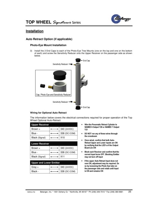
                          3)  Install the 2 End Caps to each of the Photo-Eye Tree Mounts (one on the top and one on the bottom
                             of each) and screw the Sensitivity Reducer onto the Upper Receiver on the passenger side as shown
                             below.
                                                                     End Cap
                                            Sensitivity Reducer


                              Cap, Photo Eye and Sensitivity Reducer

                                            Sensitivity Reducer

                                                                     End Cap

                          Wiring for Optional Auto Retract
                          The information below covers the electrical connections required for proper operation of the Top
                          Wheel Optional Auto-Retract.
                           Upper Receiver                          ·  Wire the Pneumatic Retract Cylinder to
                                                                      NAMED 6 Output Y20 or NAMED 7 Output
                           Brown +                340 (24VDC)         Y21
                           Blue -                 338 (DC COM)     ·  DO NOT run any of these wires through
                                                                      the crossbeam
                           Black (Signal)         X10
                                                                   ·  Once wired, confirm that both Auto-
                                                                      Retract Upper and Lower inputs are ON
                           Lower Receiver
                                                                      by verifying that the LED’s of the Output
                           Brown +                340 (24VDC)         Board are ON
                           Blue -                 338 (DC COM)     ·  Block each Receiver and confirm that the
                                                                      correct Input turns OFF. Blocking Emitter
                           Black (Signal)         X11                 may not turn off Input

                                                                   ·  If the upper Auto-Retract Input does not
                           Upper and Lower Emitter                    com ON, adjustment may be required. Do
                                                                      so by loosening the Photo Eye tube on
                           Gray +                 340 (24VDC)
                                                                      the passenger side and rotate until Input
                           Black -                338 (DC COM)        is ON and remains ON


                       1MANUL752            Belanger, Inc. * 1001 Doheny Ct. * Northville, MI 48167 * Ph (248) 349-7010 * Fax (248) 380-9681        25
   24   25   26   27   28   29   30   31   32   33   34