
Page 21 - AirBlade® Dryer Signature® Series
P. 21
AIRBLADE® DRYER Signature ® Series
Installation
AirBlade®, Frame Assembly
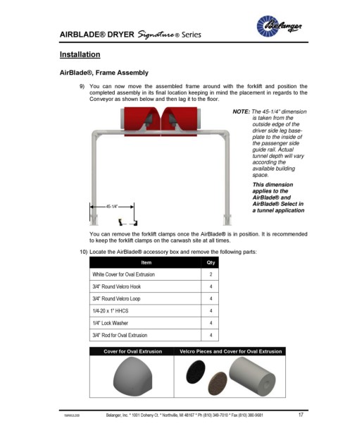
9) You can now move the assembled frame around with the forklift and position the
completed assembly in its final location keeping in mind the placement in regards to the
Conveyor as shown below and then lag it to the floor.
NOTE: The 45-1/4” dimension
is taken from the
outside edge of the
driver side leg base-
plate to the inside of
the passenger side
guide rail. Actual
tunnel depth will vary
according the
available building
space.
This dimension
applies to the
AirBlade® and
AirBlade® Select in
45-1/4”
a tunnel application
You can remove the forklift clamps once the AirBlade® is in position. It is recommended
to keep the forklift clamps on the carwash site at all times.
10) Locate the AirBlade® accessory box and remove the following parts:
Item Qty
White Cover for Oval Extrusion 2
3/4” Round Velcro Hook 4
3/4” Round Velcro Loop 4
1/4-20 x 1” HHCS 4
1/4” Lock Washer 4
3/4” Rod for Oval Extrusion 4
Cover for Oval Extrusion Velcro Pieces and Cover for Oval Extrusion
1MANUL009 Belanger, Inc. * 1001 Doheny Ct. * Northville, MI 48167 * Ph (810) 349-7010 * Fax (810) 380-9681 17