
Page 280 - Foton Workshop Manual - Auman EST-M
P. 280
DI - 226 Diagnosis - Diagnosis-fault diagnosis of electronic and electrical parts
Failure phenomenon Phenomenon description
Press the headlight height adjustment switch, but the headlight height can not be
The height of high beam is not
adjusted. Take the left front combination light as an example, the right front combination
adjustable
light shall be checked with the same method.
Diagnosis procedure
1. Check headlight adjustment switch, left front light adjusting motor power line
a. Ignition switch:LOCK.
b. Disconnect the connector B012 of high beam adjusting switch
c. Disconnect the connector B004 of left front light regulating motor
d. Ignition switch: ON, turn on the low beam.
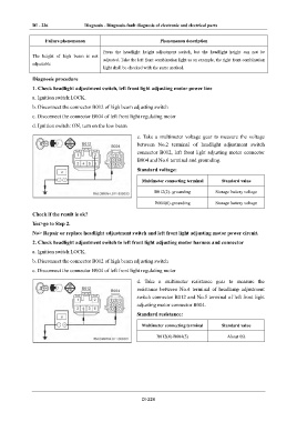
e. Take a multimeter voltage gear to measure the voltage
between No.2 terminal of headlight adjustment switch
connector B012, left front light adjusting motor connector
B004 and No.6 terminal and grounding.
Standard voltage:
Multimeter connecting terminal Standard value
B012(2)- grounding Storage battery voltage
B004(6)-grounding Storage battery voltage
Check if the result is ok?
Yes>go to Step 2.
No> Repair or replace headlight adjustment switch and left front light adjusting motor power circuit.
2. Check headlight adjustment switch to left front light adjusting motor harness and connector
a. Ignition switch:LOCK.
b. Disconnect the connector B012 of high beam adjusting switch
c. Disconnect the connector B004 of left front light regulating motor
d. Take a multimeter resistance gear to measure the
resistance between No.4 terminal of headlamp adjustment
switch connector B012 and No.5 terminal of left front light
adjusting motor connector B004.
Standard resistance:
Multimeter connecting terminal Standard value
B012(4)-B004(5) About 0Ω
DI-226