
Page 2335 - Foton Workshop Manual - Tunland (AT)
P. 2335
WIRING - SYSTEM CIRCUIT DIAGRAM 71-133
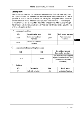
Description:
When the ignition switch is ON, the current passes through fuse F26 in the body fuse
box to pin 1 of diesel filter & heater relay R9 in the engine compartment fuse box and is
grounded at pin 2 via the coil. When the coil is energized, a magnetic field is produced
and the contact is closed. When the battery current flows from fuse F7 in the engine
compartment fuse box to pin 3 of the diesel filter & heater relay. After passing through
the contact, it outputs from pin 5 to pin A of the diesel filter & heater and is grounded via
pin B to activate the system.
: component position
NO. Ref. wiring harness NO. Ref. wiring harness
Engine compartment Front instrument
A020 C037
harness harness
71
Engine compartment
A020
harness
: connectors between wiring harnesses
Ref. wiring harness
NO. NO.
(connector position)
Front instrument harness and
engine compartment harness
C102 A303
(left side of instrument
crossbeam)
: Earthing
NO. Earth point NO. Earth point
A1 Left side of battery A5 Left side of battery
Page 2335