
Page 2333 - Foton Workshop Manual - Tunland (AT)
P. 2333
WIRING - SYSTEM CIRCUIT DIAGRAM 71-131
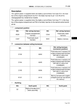
Description:
The ignition power is supplied when the battery current flows from fuse F2 in the fuse
box of the engine compartment via F8 in the body fuse box to pin 13 & 26 of the
disengageable four-wheel drive module.
The ignition power is supplied when the battery current flows from fuse F11 in the fuse
box of the engine compartment via F36 in the body fuse box to the central control switch
group.
: component position
NO. Ref. wiring harness NO. Ref. wiring harness
Engine compartment Front instrument
A020 C040
harness harness
Front instrument 71
C037 K001 Battery harness
harness
: connectors between wiring harnesses
Ref. wiring harness
NO. NO.
(connector position)
Front instrument harness and
engine compartment harness
C102 A303
(left side of instrument
crossbeam)
Front instrument harness and
engine compartment harness
C104 A305
(left side of instrument
crossbeam)
Front instrument harness and
engine compartment harness
C105 A306
(left side of instrument
crossbeam)
Battery harness and engine
K101 A110 compartment harness (below
the battery)
: Earthing
NO. Earth point NO. Earth point
Right of the electronic
B7 — —
clock assembly
Page 2333