
Page 2337 - Foton Workshop Manual - Tunland (AT)
P. 2337
WIRING - SYSTEM CIRCUIT DIAGRAM 71-135
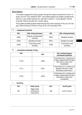
Description:
• The system supplies the battery power through the engine compartment fuse F10,
to pin 14 of the TCU controller P001. The system passes the engine compartment
fuse F2, to the indoor fuse box F2, and then to the pin 1 of the gearshift handle
controller P002 to provide the P switch signal.
The system provides ignition power through the indoor fuse box F19 to pin 6 of the
gear shift mechanism P002 and 9 pin of the TCU controller P001.
:component position
NO. Ref. wiring harness NO. Ref. wiring harness
Engine compartment
A020 P002 Gearbox harness
harness
C037 Gearbox harness P001 Gearbox harness 71
Front instrument Front instrument
C063 C056
harness harness
: connectors between wiring
NO. Ref. wiring harness
NO.
(connector position)
Front instrument harness and
engine compartment harness
C105 A306
(left side of instrument
crossbeam)
Front instrument harness and
C714 P201 gearbox harness (under
secondary instrument )
Front instrument harness and
engine compartment harness
C102 A303
(left side of instrument
crossbeam)
:Earthing
NO. Earth point NO. Earth point
Right of the
B3 combination B6 Left A column
instrument
Page 2337