
Page 2287 - Workshop Manual - Tunland (2017)
P. 2287
WIRING - SYSTEM CIRCUIT DIAGRAM 71-87
Description:
• When the ignition is in the ON/ST position, the current flows from fuse F31 of the
instrument panel fuse box to reverse light switch pin 1, from reverse light switch
pin 2 to reverse radar controller pin 2, the reverse signal is input.
• Reverse radar
The left reverse radar probe 2 pin provides the power signal and ground through
the 1 pin to provides the sensor signal.
The right reverse radar probe 2 pin provides the power signal and ground through
the 1 pin to provides the sensor signal.
Service tips
71
• E002 Reverse light switch
1-2: When the control mechanism of the transmission is engaged in the reverse
gear, the revese radar is on.
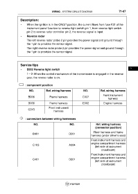
: component position
NO. Ref. wiring harness NO. Ref. wiring harness
Front instrument
B006 Frame harness C037
harness
B009 Frame harness E002 Engine harness
Front instrument
C015
harness
: connectors between wiring harnesses
NO. NO. Ref. wiring harness
(connector position)
Floor harness and frame
B401 D201
harness (under driver's seat)
Front instrument harness and
engine compartment harness
C103 A304
(left side of instrument
crossbeam)
Front instrument harness and
engine compartment harness
C401 D301
(left side of instrument
crossbeam)