
Page 210 - Zoo Animal Learning and Training
P. 210
Chapter 25: Vertebral Fracture and Luxation Repair 215
A
D
B
E
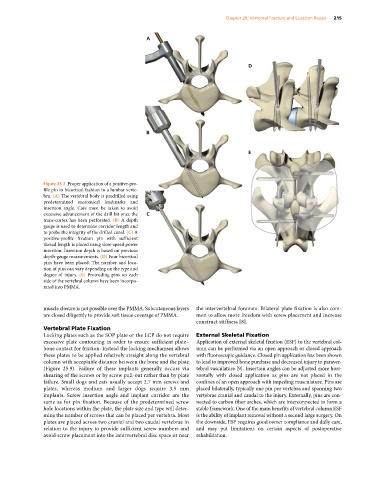
Figure 25.7 Proper application of a positive‐pro
file pin in bicortical fashion in a lumbar verte
bra. (A) The vertebral body is predrilled using
predetermined anatomical landmarks and
insertion angle. Care must be taken to avoid
excessive advancement of the drill bit once the C
trans‐cortex has been perforated. (B) A depth
gauge is used to determine corridor length and
to probe the integrity of the drilled canal. (C) A
positive‐profile fixation pin with sufficient
thread length is placed using slow‐speed power
insertion. Insertion depth is based on previous
depth‐gauge measurements. (D) Four bicortical
pins have been placed. The number and loca
tion of pins can vary depending on the type and
degree of injury. (E) Protruding pins on each
side of the vertebral column have been incorpo
rated into PMMA.
muscle closure is not possible over the PMMA. Subcutaneous layers the intervertebral foramen. Bilateral plate fixation is also com
are closed diligently to provide soft tissue coverage of PMMA. mon to allow more freedom with screw placement and increase
construct stiffness [8].
Vertebral Plate Fixation
Locking plates such as the SOP plate or the LCP do not require External Skeletal Fixation
excessive plate contouring in order to ensure sufficient plate– Application of external skeletal fixation (ESF) to the vertebral col
bone contact for friction. Instead the locking mechanism allows umn can be performed via an open approach or closed approach
these plates to be applied relatively straight along the vertebral with fluoroscopic guidance. Closed pin application has been shown
column with acceptable distance between the bone and the plate to lead to improved bone purchase and decreased injury to paraver
(Figure 25.9). Failure of these implants generally occurs via tebral vasculature [9]. Insertion angles can be adjusted more hori
shearing of the screws or by screw pull‐out rather than by plate zontally with closed application as pins are not placed in the
failure. Small dogs and cats usually accept 2.7 mm screws and confines of an open approach with impeding musculature. Pins are
plates, whereas medium and larger dogs require 3.5 mm placed bilaterally, typically one pin per vertebra and spanning two
implants. Screw insertion angle and implant corridor are the vertebrae cranial and caudal to the injury. Externally, pins are con
same as for pin fixation. Because of the predetermined screw nected to carbon fiber arches, which are interconnected to form a
hole locations within the plate, the plate size and type will deter stable framework. One of the main benefits of vertebral column ESF
mine the number of screws that can be placed per vertebra. Most is the ability of implant removal without a second large surgery. On
plates are placed across two cranial and two caudal vertebrae in the downside, ESF requires good owner compliance and daily care,
relation to the injury to provide sufficient screw numbers and and may put limitations on certain aspects of postoperative
avoid screw placement into the intervertebral disc space or near rehabilitation.