
Page 388 - Adams and Stashak's Lameness in Horses, 7th Edition
P. 388
354 Chapter 3
VetBooks.ir
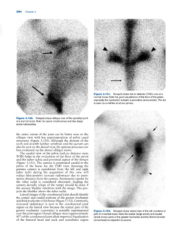
Figure 3.151. Delayed phase tail on detector (TOD) view of a
normal horse. Note the good visualization of the floor of the pelvis,
especially the symmetric ischiatic tuberosities (arrowheads). The tail
is seen as a midline structure (arrow).
Figure 3.150. Delayed phase oblique view of the sacroiliac joint
of a normal horse. Note the sacral (small arrow) and iliac (large
arrow) tuberosities.
the entire extent of the joint can be better seen on the
oblique view with less superimposition of pelvic canal
structures (Figure 3.150). Although the dorsum of the
sixth and seventh lumbar vertebrae and the sacrum can
also be seen on the dorsal view, the spinous processes are
best evaluated on the dorsal oblique views.
The caudal view of the pelvis (tail‐on detector view,
TOD) helps in the evaluation of the floor of the pelvis
and the tuber ischia and proximal aspect of the femurs
(Figure 3.151). The camera is positioned caudal to the
pelvis of the horse for the TOD view. Ensuring the
gamma camera is equidistant from the left and right
tuber ischii during the acquisition of this view will
reduce false‐positive increase radiotracer due to asym
metric distance from the camera. Asymmetric uptake by
the tuber ischii is considered abnormal. Angling the
camera dorsally (slope of the rump) should be done if
the urinary bladder interferes with the image. This pro
jects the bladder above the tuber ischii.
Lateral images of the coxofemoral joint should identify
the cranial and caudal portions of the greater trochanter
and third trochanter of the femur (Figure 3.152). Commonly,
increased radiotracer is seen in the coxofemoral joint
region on the lateral view because the cranial part of the
greater trochanter (convexity) is partially superimposed Figure 3.152. Delayed phase lateral view of the left coxofemoral
over the joint region. Dorsal oblique views (approximately joint of a normal horse. Note the cranial (large arrow) and caudal
45°) of the coxofemoral joint allow improved visualization (small arrow) parts of the greater trochanter and the third trochanter
of the femoral head and neck and acetabular region (arrowhead) as separate structures.